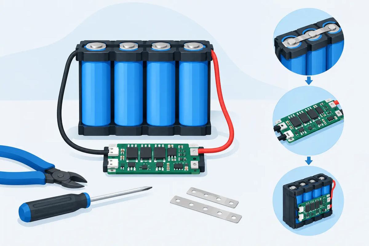
A 4S lithium-ion pack can look straightforward on the bench: four series cell groups, a BMS, nickel strip and a pair of output leads. The catch is that one balance lead on the wrong group can destroy the BMS in seconds. To install a 4S BMS correctly, you need to identify each series node before soldering anything, then follow the terminal order specified for that exact board.
This guide is for standard 4S lithium-ion chemistry using 18650, 20700 or 21700 cells. A typical pack is 14.8V nominal and 16.8V when fully charged. It is not automatically suitable for a 4S LiFePO4 pack, which has a different charge voltage and needs a BMS designed for that chemistry.
Confirm the BMS suits the pack
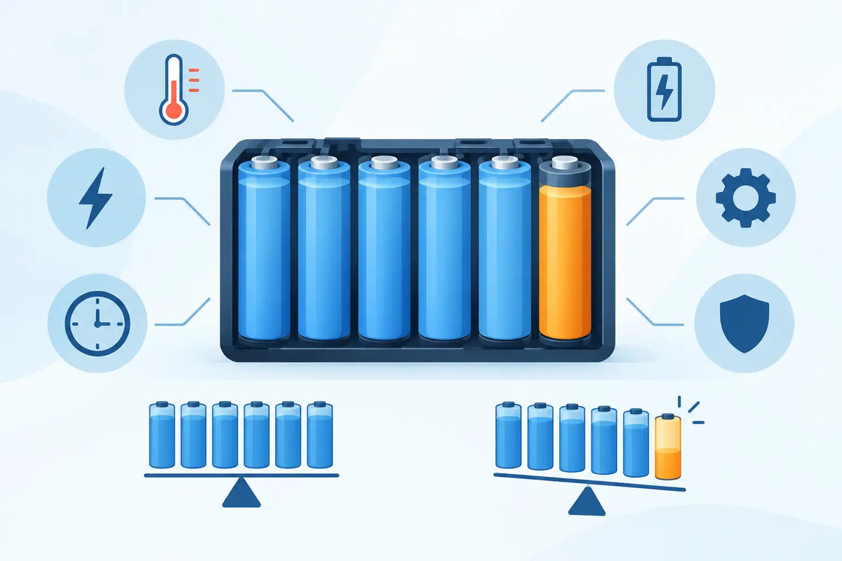
A 4S BMS monitors four series-connected groups, not necessarily four individual cells. A 4S2P pack, for example, has eight cells arranged as four parallel pairs in series. Each parallel group is treated as one cell group by the BMS.
Start by checking the continuous discharge current rating. A 20A BMS is not a good match for a load that routinely draws 20A. Heat, peak current and the board's real-world cooling all matter. For an e-bike conversion, scooter, high-output torch or inverter project, allow sensible current headroom. For a low-current LED, portable radio or battery storage project, a lower-current board may be suitable.
Also check whether the BMS has balancing, temperature sensing and separate charge and discharge ports. Basic boards often have B-, B1, B2, B3, B+ and P- terminals. On these boards, pack positive is commonly shared between the charger and load. Other boards have separate P- and C- terminals, while some use a dedicated C+ or P+ connection. Terminal labels vary, so the printing on the board and its wiring diagram always take priority over a generic diagram.
Check cell groups before wiring
Use matched cells from the same model and condition. In a parallel group, cells should be brought to nearly the same voltage before joining them. In a series pack, each completed group should also be close in voltage before the BMS is connected.
For a new 4S build, measure from the overall pack negative and write down the voltage at every series node. You should see approximately:
- B- or pack negative: 0V
- B1: roughly one cell-group voltage, often 3.0V to 4.2V
- B2: roughly two group voltages, often 6.0V to 8.4V
- B3: roughly three group voltages, often 9.0V to 12.6V
- B+ or pack positive: roughly 12.0V to 16.8V
Prepare the pack and work area
Spot welding is the preferred method for attaching nickel strip to cylindrical cells. Soldering directly to a cell can overheat it, damage the internal seal or shorten service life. If you are repairing an existing pack, inspect every nickel connection, insulator ring and fish-paper barrier before reusing it.
Keep the balance wires short enough to be protected, but long enough that the BMS can sit without pulling on them. Add insulation wherever nickel strip, BMS pads or wire could contact another conductive part. A BMS is not a substitute for proper pack construction.
Before you start, have a multimeter ready and remove jewellery such as rings and metal watch bands. A single accidental short across a high-discharge lithium-ion pack can generate enough heat to burn nickel, wire insulation and skin very quickly.
Install the 4S BMS in the correct order
The safest method is to connect the sense points in sequence from pack negative towards pack positive. Many 4S boards use this order: B-, B1, B2, B3, then B+. Check your particular board first. Some balance harnesses use a plug with coloured wires, but wire colours are not a reliable substitute for meter readings.
Connect the negative and balance terminals
First, connect the B- pad or lead to the pack's overall negative terminal. This is the negative end of series group one, not the negative terminal of a group in the middle of the pack.
Next connect B1 to the positive side of group one. Connect B2 to the positive side of group two, B3 to the positive side of group three, and B+ to the overall pack positive terminal. If the board uses a balance connector rather than individual pads, confirm the pinout with a multimeter before inserting it. The first pin is usually B-, but “usually” is not a safe wiring instruction.
After each connection, measure the voltage between B- and the newly connected sense point. The readings should step up by approximately one group voltage each time. If the BMS becomes warm, a wire sparks, or a reading is unexpected, disconnect it immediately and recheck the series-node map.
Avoid connecting the balance plug in a random order after the pack has been assembled. Some BMS designs can tolerate this, while others can be damaged if a higher-voltage sense lead reaches the board before its lower reference lead. Following the manufacturer sequence is the low-risk option.
Connect charge and discharge leads
On a common-port BMS, the load negative and charger negative both connect to P-. The load positive and charger positive usually connect directly to B+, which is pack positive. This arrangement lets the BMS control the negative side when it detects over-current, short circuit, over-charge or low cell voltage.
On a separate-port BMS, connect the load negative to P- and the charger negative to C-. Again, the positive leads normally go to pack positive unless the board documentation says otherwise. Do not bridge P- and C- because it seems convenient. Doing so can bypass part of the protection function.
Use wire gauge that suits the expected continuous current and keep high-current leads as short as practical. Thin silicone wire may be fine for balance connections but is not suitable for a 30A discharge path. If the pack will be used in a device with high fault energy, fit an appropriately rated fuse close to pack positive. A fuse protects wiring against catastrophic faults that a BMS may not clear fast enough.
Test before putting the pack into service
Once wired, measure the voltage at the output terminals. If the BMS is awake and no protection condition is active, you should see pack voltage between P- and pack positive. A reading of 0V does not always mean the board has failed. Some BMS units ship in protection mode and need a compatible charger connected briefly to wake them.
Charge the pack with a charger designed for 4S lithium-ion - 16.8V constant-voltage output. Do not use a 12V lead-acid charger, a random laptop power supply or a 4S LiFePO4 charger. During the first charge, stay nearby and periodically check that the BMS, wires and connections remain cool.
Then test the intended load at a modest current before asking for full output. Check voltage at the pack and at the device under load. A large voltage drop can indicate undersized wiring, a weak nickel connection, unsuitable cells or a BMS that is too small for the application.
Common faults after BMS installation
If the output is dead but each group measures normally, inspect the BMS terminal sequence and look for a disconnected B- lead. If charging works but discharge does not, confirm that the load is connected to P- rather than directly to B-. If discharge works but charging does not, check whether the board has a separate C- terminal.
A BMS that cuts out under acceleration or when a motor starts may be responding correctly to an over-current spike. Measure actual current where possible, then choose a BMS and cells that can handle both the continuous draw and the peak demand. Increasing the BMS rating alone will not fix cells that are being pushed beyond their safe discharge rating.
Cell imbalance is another warning sign. Passive balancing on many compact BMS boards is slow and often only begins near full charge. It can maintain a healthy matched pack, but it cannot rescue a pack built from mixed, worn or badly mismatched cells.
Mount the finished board where it cannot rub against nickel strip or the enclosure. Cover exposed pads with suitable insulation, strain-relieve the leads and leave enough access to inspect the pack later. Careful BMS wiring is not glamorous, but it is what turns a collection of cells into a pack you can charge and use with confidence.