
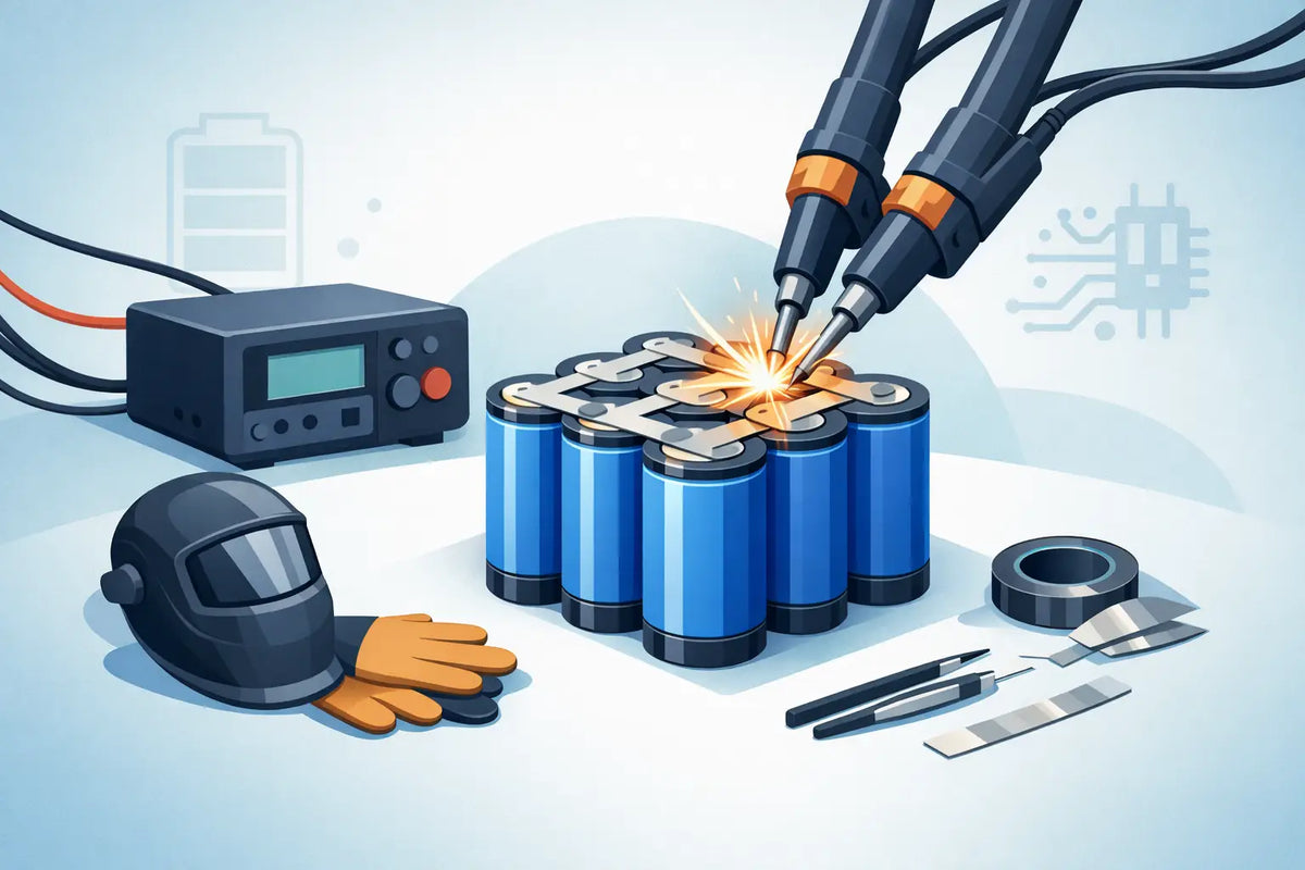
A lithium-ion cell can deliver enough current to turn a misplaced strip of metal into a red-hot link in seconds. That is why learning how to weld cells safely is less about making neat weld marks and more about controlling every opportunity for a short circuit, overheating or cell damage.
For most DIY battery packs, welding means resistance spot welding nickel strip to the cell terminals. It is not arc welding, and it is not a job for a soldering iron held against the cell can. A suitable spot welder puts a short, localised pulse through the strip, attaching it to the terminal before heat travels deeply into the cell. Done properly, it is fast, repeatable and far safer than trying to solder directly to a bare cylindrical cell.
Start with cells that belong in the same pack
A safe weld begins before the spot welder is switched on. Use new, genuine cells of the same model, capacity and condition for a new pack. Do not combine an 18650 with a 21700, mix high-drain and capacity-focused cells, or add one new cell to a group of aged cells. Cells connected in parallel need to sit at closely matched voltages before joining. Cells in series must also be matched by model and preferably by measured capacity and internal resistance.
Check every cell under good light. Set aside anything with a torn wrap, dented can, damaged positive insulator ring, corrosion, leaking electrolyte or unusual odour. Do not weld a cell that has been dropped hard, overheated, over-discharged or removed from an unknown pack. The cost of a replacement cell is minor compared with the risk of building a fault into a pack.
If you are rebuilding a battery, treat salvaged cells as a testing project rather than automatic pack material. Capacity, self-discharge and internal resistance all need checking. For a dependable portable-power, e-bike or high-current build, matched new cells are usually the sensible option.
Set up a workspace that limits consequences
Lithium-ion pack work needs a clean, non-flammable bench with room to keep conductive items away from live terminals. Work on a ceramic tile, metal bench with an insulating top, or another heat-resistant surface. Avoid carpet, timber offcuts, cluttered sheds and benches covered in screws, wire clippings or nickel-strip scraps.
Keep a suitable fire extinguisher nearby and know how to leave the area safely if a cell vents. A bucket of dry sand can help contain a small battery fire, while water can cool surrounding materials and limit fire spread where it is safe to do so. Never pick up or handle a venting cell. Its fumes are hazardous, and thermal runaway can intensify without warning.
Before starting, remove watches, rings, bracelets and necklaces. Wear safety glasses. Use insulated tools where practical, and keep one hand clear when positioning probes so you are less likely to bridge terminals accidentally. Good ventilation is sensible, particularly when working with heat-shrink, fish paper or a cell that may have been compromised.
Have your materials laid out before cells come onto the bench:
- a spot welder with clean, undamaged electrodes
- correctly sized pure nickel strip or verified nickel-plated steel strip
- fish paper rings, insulating sheets, cell spacers and heat-shrink
- a multimeter, side cutters and non-conductive tape
- the correct BMS, balance wiring and fuse wire if the design requires them
Choose the strip and welder settings carefully
Nickel strip is part of the electrical design, not merely a fastening material. Its width and thickness must safely carry the expected current. A high-discharge 21700 pack powering a motor needs a more considered interconnect design than a low-current torch pack. Undersized strip can heat up under load, lose weld strength and create voltage drop.
Pure nickel is generally preferred because its electrical properties are predictable and it resists corrosion. Some nickel-plated steel strip is suitable for particular builds, but it has higher resistance and varies widely in quality. Check what you have rather than assuming every silvery strip is pure nickel.
Set the spot welder by testing on spare cells or, better still, on scrap nickel over a discarded cell terminal. Start at a conservative setting and increase only enough to form reliable welds. A good weld holds firmly when the strip is peeled sideways with pliers, leaving small witness marks rather than burning a hole through the strip or terminal.
Too little energy produces weak welds that can fail under vibration. Too much energy can puncture strip, damage the terminal cap, melt the cell seal or create unnecessary heat. Pulse settings depend on strip thickness, electrode condition and the specific welder, so there is no single setting that suits every machine.
Keep electrode tips clean and evenly shaped. Dirty or oxidised tips create inconsistent resistance, which makes weld quality unpredictable. Place both electrodes squarely on the nickel strip with firm, steady pressure. Do not let them touch each other while the welder is armed, and do not weld across a cell casing or near the edge of the positive terminal insulator.
How to weld cells safely, one connection at a time
Arrange the cell layout first and confirm the series and parallel path against your wiring diagram. Mark positive and negative ends clearly. A single reversed cell in a series group can create a direct fault as soon as the interconnect is fitted.
Fit fish paper insulating rings over every positive terminal before welding. The positive cap is separated from the negative can by a thin insulating gasket. Nickel strip placed too close to that edge, or a damaged ring, can bridge positive to negative and short the cell. This is one of the most important details in cylindrical-cell pack building.
Weld only the intended terminal surface. On the positive end, keep welds centred on the cap and away from its perimeter. On the negative end, weld on the flat base. Use two or more well-spaced weld points as required by the strip and current path, rather than concentrating excessive energy in one spot.
After each weld, let the terminal cool briefly and check it. The cell should not become hot to the touch. If it does, stop and review your pulse setting, electrode pressure and strip material. Heat is feedback, not something to work through.
Build in stages. Complete a parallel group, inspect for stray strip and confirm its voltage, then move to the next connection. Keep completed conductive paths covered with fish paper or other insulation as you go. Never lay a loose strip, screwdriver or multimeter probe across an unfinished pack.
Avoid welding directly over balance-wire joins or BMS leads. Where a lead must connect to a cell group, weld a nickel tab first and solder the wire to the tab away from the cell. This keeps soldering heat off the cell terminal and makes future servicing less hazardous.
Protect the pack after the welds are done
A pack is not finished when the nickel is attached. Check each series-group voltage with a multimeter and confirm the total voltage matches the design. Measure for continuity only where expected. If a reading does not make sense, stop before connecting a charger, BMS or load.
Install the correct BMS for the number of series groups and the real continuous current of the application. A BMS is not a substitute for sound welding or insulation, but it provides essential protection against over-charge, over-discharge and excessive current when correctly selected and wired. Follow its balance-lead sequence exactly. Connecting sense wires in the wrong order can damage the BMS immediately.
Cover exposed nickel, cell ends and sharp edges with fish paper, insulating barriers and suitable heat-shrink. Use cell holders or spacers where appropriate to prevent rubbing and movement. For packs exposed to vibration, such as mobility, bike or tool applications, mechanical support matters as much as electrical connection quality.
Before putting the pack into service, charge it under supervision using a charger matched to the chemistry and series count. Check for abnormal temperature rise during charging and on the first controlled discharge. A new pack should not be left charging unattended, especially while you are confirming that the BMS, balance connections and current path behave as intended.
Safe pack building rewards patience. If a cell, weld or voltage reading looks questionable, isolate it and investigate before continuing. A clean layout, matched cells, correct nickel and careful insulation will do more for a reliable battery pack than rushing to finish the last few welds.