
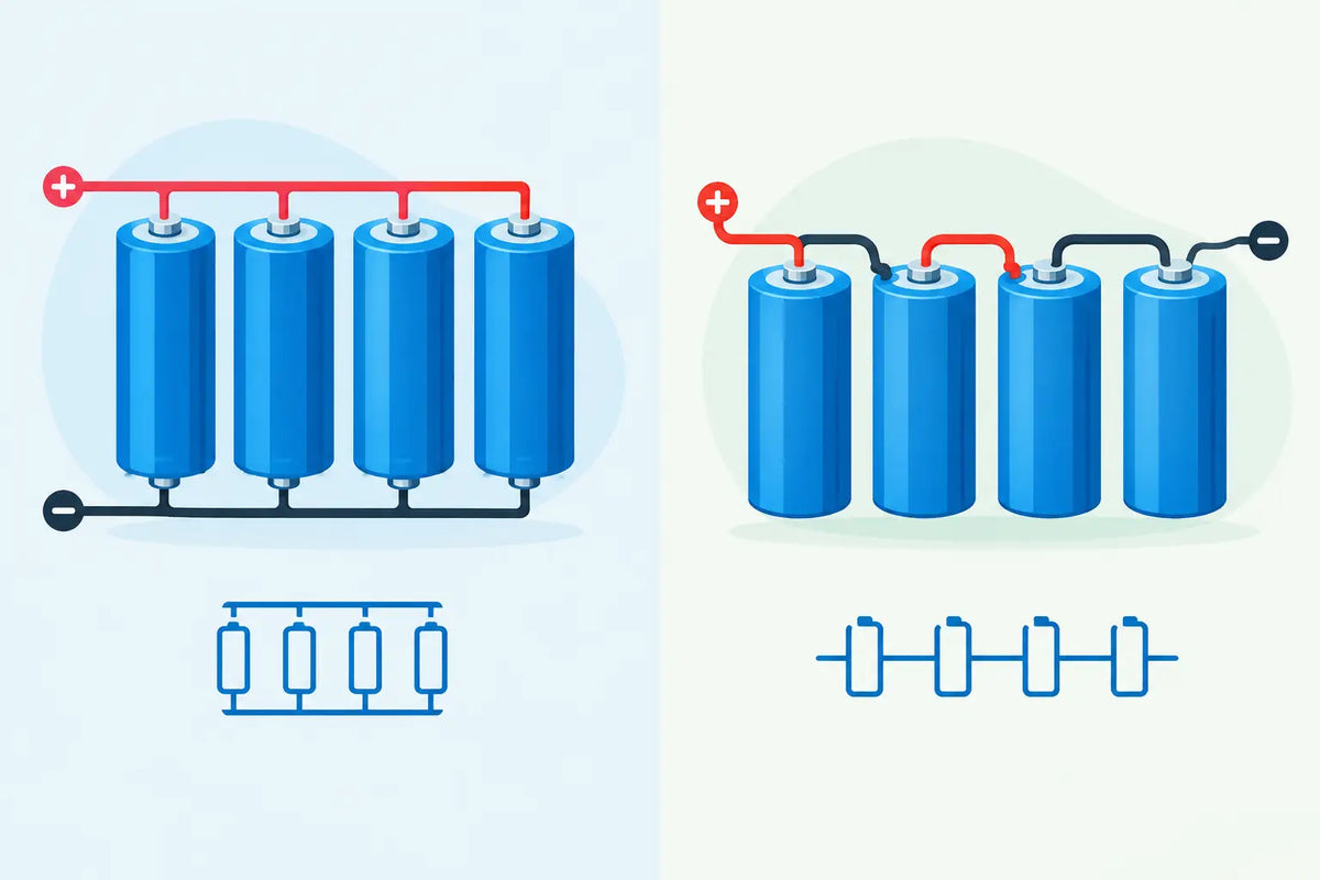
A 21700 cell that runs a high-output torch is not automatically the right building block for an e-bike battery. The difference usually comes down to pack configuration. Understanding parallel versus series packs tells you whether a build will deliver the required voltage, runtime and current - and whether the BMS, nickel strip and cells are correctly matched.
For lithium-ion pack building, there is no universally better arrangement. Series connections raise voltage. Parallel connections raise capacity and available current capability. Most practical battery packs use both.
Parallel versus series packs: the core difference
A series connection joins cells end-to-end: positive of one cell to negative of the next. The voltage adds, while capacity in amp-hours stays the same.
If four 3.6V nominal, 5.0Ah cells are connected in series, the result is a 4S1P pack. It has a nominal voltage of 14.4V and a capacity of 5.0Ah. At full charge, assuming standard 4.2V lithium-ion cells, it reaches 16.8V. Each cell carries the same pack current, so the cells must each be capable of handling the load.
A parallel connection joins all positives together and all negatives together. Voltage stays the same, while capacity adds. Three matching 5.0Ah cells connected in parallel make a 1S3P group: nominally 3.6V, with 15.0Ah capacity.
A pack designation combines these two ideas. A 10S4P battery contains ten series-connected groups, with four cells in parallel within each group. For a 3.6V nominal cell, that gives approximately 36V nominal. If each cell is 4.0Ah, pack capacity is 16Ah. The pack contains 40 cells in total.
What changes in each configuration
| Configuration | Voltage | Capacity | Current capability |
| --- | --- | --- | --- |
| Series | Adds across cells | Remains the same | Limited by one cell's rating and the weakest series group |
| Parallel | Remains the same | Adds across cells | Can increase, provided cells, interconnects and BMS support it |
| Series-parallel | Adds through series groups | Adds through parallel groups | Depends on the complete design |
Voltage and capacity are not interchangeable. A 10S1P pack and a 5S2P pack both contain ten cells, but they suit entirely different equipment. The 10S1P pack is roughly 36V nominal and 5Ah. The 5S2P pack is roughly 18V nominal and 10Ah. Their stored energy in watt-hours can be similar, but their device compatibility is not.
Start with the device voltage
Voltage should be the first design decision because the controller, motor, electronics or appliance expects a defined input range. Connecting too few series groups may cause a device to cut out or perform poorly. Connecting too many can destroy electronics, exceed a controller's voltage rating or create an unsafe charging arrangement.
Check the device label, existing battery specification and charger output before deciding on series count. A battery described as 36V lithium-ion is commonly 10S, with a 42V full-charge voltage. A 48V lithium-ion pack is commonly 13S and charges to 54.6V. These are common examples, not assumptions to apply blindly. Different lithium chemistries and systems use different voltage limits.
Once series count is fixed, choose the number of parallel cells according to runtime and load current. This is where capacity-focused and high-discharge cells lead to different pack designs.
Capacity, runtime and watt-hours
Cell capacity is normally stated in milliamp-hours, such as 3000mAh or 5000mAh. In parallel, capacities add. Four matched 3000mAh cells in a parallel group provide 12,000mAh, or 12Ah, at the voltage of one cell.
Runtime is better estimated in watt-hours because it accounts for voltage as well as amp-hours. The basic calculation is:
Watt-hours = nominal pack voltage × pack capacity in amp-hours
For example, a 10S4P pack made from 3.6V nominal, 4.0Ah cells is approximately 36V and 16Ah. That is about 576Wh. Actual usable energy will be lower or higher depending on cell voltage curve, discharge rate, BMS cut-off settings, temperature and the condition of the cells.
Adding cells in series raises voltage and total energy, but it does not increase amp-hour capacity. Adding cells in parallel raises amp-hour capacity and total energy, while leaving voltage unchanged. This distinction prevents a common design error: choosing more series cells when the real requirement is longer runtime.
Current rating is a pack-level calculation
A cell's continuous discharge rating matters as much as its mAh rating. High-capacity cells can be ideal for lower-current loads, while high-drain cells are often the better choice for e-bikes, scooters, power tools and other demanding applications.
In a parallel group, the continuous cell rating can be multiplied by the number of cells, but only as a starting point. Four genuine 15A continuous-discharge cells in parallel may provide 60A of cell capability on paper. The finished pack is only safe for that current if the nickel strip or copper interconnects, spot welds, BMS, wiring, connectors and fuse arrangement are all rated accordingly.
In a series string, the same current passes through every series group. A 13S1P pack using 15A cells remains a 15A continuous pack at best, not a 195A pack. Its higher voltage can deliver more power at the same current, but the current limit does not add across series cells.
Allow margin rather than building exactly to a rating. Cell ratings are measured under specified conditions, and heat, restricted airflow and repeated hard use reduce the comfort margin. A pack that runs cool at the intended continuous load will generally last longer than one pushed to its limit.
Cell matching matters more in series strings
Every cell in a DIY pack should be the same chemistry, format, model and condition. Do not mix 18650 and 21700 cells, new and heavily used cells, different capacities, or cells from different manufacturers in the same pack. Similar dimensions or nominal voltage do not make cells electrically compatible.
Before building parallel groups, cells should be brought to closely matched voltages. Connecting cells at significantly different voltages in parallel can cause a very high equalisation current. That current is uncontrolled, can damage cells or connections, and is not a substitute for charging.
Series groups need close matching because the weakest group reaches full or empty first. Over time, mismatch can cause one group to hit BMS high-voltage or low-voltage protection early, reducing usable pack capacity. In more serious cases, an unbalanced pack can place individual cells outside their safe operating range if the protection system is incorrect or bypassed.
For reclaimed cells, test capacity and internal resistance, then group cells with closely matched results. For a new build, starting with genuine, identical cells from the same batch is the simpler and more dependable approach.
Choose a BMS for the actual series count
A battery management system is selected primarily by chemistry and series count. A 10S lithium-ion BMS is for a 10-series-group pack, whether each group is 1P, 4P or 10P. A 13S BMS is not interchangeable with a 10S BMS simply because both are used in higher-voltage packs.
The BMS must also suit the expected continuous and peak current. Its discharge rating, charge rating, balance current, temperature sensing provisions, wire gauge and connector arrangement all matter. A BMS cannot turn undersized cells or thin nickel strip into a high-current battery.
Use the correct balance-lead order and verify every group voltage before plugging the balance connector into the BMS. One misplaced balance wire can damage the BMS immediately. Follow the specific BMS wiring diagram, as common-port and separate charge/discharge port designs are wired differently.
Build the pack around the load, not the cell count
It is tempting to begin with cells already on hand and work backwards. For anything beyond a simple low-current project, start with the device requirements: operating voltage, peak current, continuous current, target runtime, physical space and charging method.
A compact torch may need a single protected cell or a simple 1S arrangement. A portable power project may prioritise watt-hours and moderate current. An e-bike or scooter pack needs a defined series count, a realistic current margin, a correctly rated BMS and substantial attention to insulation, mechanical support and interconnect design.
Spot weld cells rather than soldering directly to their terminals where possible. Heat from soldering can damage seals and internal cell components. Use appropriate cell holders or spacers, fish paper insulation, insulating rings on positive terminals and secure outer wrapping. Add fusing where the design calls for it, and prevent any possibility of a loose pack contacting conductive tools or a metal enclosure.
A well-designed pack is not the one with the biggest mAh figure on the label. It is the pack whose voltage matches the equipment, whose cells comfortably handle the load, and whose BMS and construction give every series group the protection it needs. Measure twice before making the first weld - correcting a pack on the bench is far easier than diagnosing one after it is sealed into a bike, tool or portable power box.